
I'd agree that the controller only gets warm, not hot. I'd use the temp sensor, especially since you say there is a big temp diff in your setup.
21 replies to this topic
#11

Vic Harder
-

- Site Team
- 4,950 posts
Doctor Electric
- LocationCalgary, Alberta
Posted 09 December 2019 - 12:31 AM
2015 Silverado 3500 crew cab 8' bed Diesel
2012 ATC Puma Shell build - https://www.wanderth...012-puma-build/
Power considerations thread - https://www.wanderth...e-power-scotty/
Building out an electrical system - So, you want to setup a good electrical system in your camper? - Electrical, Charging, Solar, Batteries and Generators - Wander the West
#12
Redfish
-

- Members
-

- 55 posts
Advanced Member
- LocationNorth-Central Florida
Posted 10 December 2019 - 06:40 PM
Thanks, Desert Scruff and Vic. I may end up mounting in the cabinet above the batteries, though I hate to lose the space. I'll install the temp sensor, too, then. And apologies to the OP for hijacking his/her thread!
Another couple of questions: My two 12V AGM batteries are wired in parallel. Does it matter which of the two battery negative terminals I connect to the BM shunt? I'm assuming I'll just attach to the negative battery terminal that currently carries two negative wires that will be relocated to the other side of the BM shunt (probably solar controller and negative bus bar).
Also, I noticed that I have two positive wires (same as above), but each connected to a different battery. Can I consolidate them on one battery positive terminal, and if so, does it matter which battery (for example, the same battery that will be wired to the BM shunt)?
Many thanks. Really looking forward to finally having a battery monitor and to losing the PWM controller.
2016 Tacoma 4x4 V6 SR5 AT
2016 FWC Fleet
#13
Vic Harder
-
- Site Team
- 4,950 posts
Doctor Electric
- LocationCalgary, Alberta
Posted 10 December 2019 - 08:14 PM
ideally, you want all the positive wires feeding your system to come off of one of the 12v batteries, and the ground wire to come off of the other battery. That way both batteries get "exercised" the same amount.
Also, the ONLY thing connected to the battery ground should be the shunt. ALL other ground wires go to the far side of the shunt.
2015 Silverado 3500 crew cab 8' bed Diesel
2012 ATC Puma Shell build - https://www.wanderth...012-puma-build/
Power considerations thread - https://www.wanderth...e-power-scotty/
Building out an electrical system - So, you want to setup a good electrical system in your camper? - Electrical, Charging, Solar, Batteries and Generators - Wander the West
2012 ATC Puma Shell build - https://www.wanderth...012-puma-build/
Power considerations thread - https://www.wanderth...e-power-scotty/
Building out an electrical system - So, you want to setup a good electrical system in your camper? - Electrical, Charging, Solar, Batteries and Generators - Wander the West
#14
Redfish
-
- Members
-
- 55 posts
Advanced Member
- LocationNorth-Central Florida
Posted 11 December 2019 - 10:28 AM
Vic,
Thanks, very helpful, and gotcha on all* negs moved to shunt far side.
Jeff
*to be clear, except for battery #1 neg to battery #2 neg parallel jumper cable
2016 Tacoma 4x4 V6 SR5 AT
2016 FWC Fleet
#15
Vic Harder
-
- Site Team
- 4,950 posts
Doctor Electric
- LocationCalgary, Alberta
Posted 11 December 2019 - 04:42 PM
Right, in a parallel setup, there are two cables on that post.
2015 Silverado 3500 crew cab 8' bed Diesel
2012 ATC Puma Shell build - https://www.wanderth...012-puma-build/
Power considerations thread - https://www.wanderth...e-power-scotty/
Building out an electrical system - So, you want to setup a good electrical system in your camper? - Electrical, Charging, Solar, Batteries and Generators - Wander the West
2012 ATC Puma Shell build - https://www.wanderth...012-puma-build/
Power considerations thread - https://www.wanderth...e-power-scotty/
Building out an electrical system - So, you want to setup a good electrical system in your camper? - Electrical, Charging, Solar, Batteries and Generators - Wander the West
#16
Redfish
-
- Members
-
- 55 posts
Advanced Member
- LocationNorth-Central Florida
Posted 06 February 2020 - 05:07 PM
As a follow-up to the questions I asked in this thread, and the helpful answers I received, I'm providing a few details and photos of my install of a Victron 100v/20a MPPT controller and Victron 712 battery monitor in my 2016 Fleet w/front dinette. Hopefully this will be helpful to others with a similar set up.
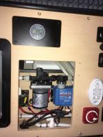
Because of limited space, I mounted the 100v/20a controller and a 100a breaker in the kitchen cabinet (1st photo). It was very tight. I could have mounted one or both in the kitchen cabinet above the battery box but wanted to save space for kitchen stuff, plus this allowed me to shorten the wiring run by about 3-4 feet. Although it may not be obvious, the breaker is wired between the controller and the batteries.
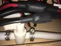
I then drilled two holes in the bottom of the cabinet and ran the pos and neg wires* from the switch into the space below the converter/charger and directly to the batteries (2nd photo below). (*Note that I used the breaker and a separate neg junction post to consolidate the solar panel and external plug wiring so that I could run single neg and pos wires to the battery box because I barely had space for the two holes owing to plumbing above and existing wiring below.)
I also installed a switch (mounted on cabinet exterior) between the panels and the controller. I upgraded all of the wiring to 8ga except the wiring coming from the solar panels/external solar plug to the controller/switch; I'll upgrade that 12ga wiring along with my flexible panels when the performance of panels becomes sufficiently degraded.
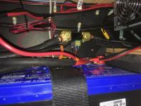
I installed the battery monitor shunt in the back of the battery cabinet (3rd photo below). I added the temp sensor to the monitor because I know that the rather isolated battery box will be significantly cooler than the kitchen cabinet-mounted controller during prolonged cold weather. I made a blank out of aluminum to fill the void in my cabinet left by the prior solar controller and used that to mount the battery monitor (see 1st photo).
I ordered online all of the components and parts from the very helpful people at AM Solar in Springfield OR. Their prices were competitive and I didn't have to source and buy all of the parts separately. Plus they install and service RV solar and use and sell only the equipment they know and trust, they've been in business for years, and were very responsive and answered all of my questions and gave great advice.
Edited by Redfish, 15 February 2020 - 02:49 PM.
2016 Tacoma 4x4 V6 SR5 AT
2016 FWC Fleet
#17
Redfish
-
- Members
-
- 55 posts
Advanced Member
- LocationNorth-Central Florida
Posted 06 February 2020 - 05:09 PM
Photo of where I drilled holes to run wires from kitchen cabinet to battery cabinet.
2016 Tacoma 4x4 V6 SR5 AT
2016 FWC Fleet
#18
Redfish
-
- Members
-
- 55 posts
Advanced Member
- LocationNorth-Central Florida
Posted 06 February 2020 - 05:12 PM
Photo of shunt location. Note that I also upgraded battery cabling to 2/0.
2016 Tacoma 4x4 V6 SR5 AT
2016 FWC Fleet
#19
Vic Harder
-
- Site Team
- 4,950 posts
Doctor Electric
- LocationCalgary, Alberta
Posted 06 February 2020 - 07:57 PM
NICE!
2015 Silverado 3500 crew cab 8' bed Diesel
2012 ATC Puma Shell build - https://www.wanderth...012-puma-build/
Power considerations thread - https://www.wanderth...e-power-scotty/
Building out an electrical system - So, you want to setup a good electrical system in your camper? - Electrical, Charging, Solar, Batteries and Generators - Wander the West
2012 ATC Puma Shell build - https://www.wanderth...012-puma-build/
Power considerations thread - https://www.wanderth...e-power-scotty/
Building out an electrical system - So, you want to setup a good electrical system in your camper? - Electrical, Charging, Solar, Batteries and Generators - Wander the West
#20
GaryRpg
-

- Members
-
- 9 posts
Newbie
Posted 24 January 2024 - 05:17 PM
On the Victron MPPT there is grounding screw on the heat sink chassis. What should this connect to?
I have to admit that I'm a bit foggy on grounding on the FWC camper. There is a bus bar next to my fuse box and I'm not sure what it connects to. Perhaps the negative on the battery?
Thanks in advance for your help!


0 user(s) are reading this topic
0 members, 0 guests, 0 anonymous users

