
Are you sure you have gas and the jet is not plugged?


Furnace won't light
Started by
natjwest
, Oct 10 2010 02:07 AM
60 replies to this topic
#51

pvstoy
-
- Members
- 2,771 posts
Senior Member
- LocationCarson City, NV
Posted 20 September 2019 - 10:00 PM
Patrick
2015 FWC Hawk Flatbed
#52
WillTheThri11
-

- Members
- 141 posts
Senior Member
- LocationSouthern California
Posted 23 September 2019 - 06:50 PM
Are you sure you have gas and the jet is not plugged?
I'm sure there's gas in the tank since i can run the fridge and stove on it just fine. Where is the jet?
#53
Sledawg
-
- Members
- 126 posts
Senior Member
Posted 12 March 2024 - 10:09 PM
My 10 year old Atwood 8012-II furnace suffered the issue of fan running and not lighting last road trip. Rather than replacing parts such as the sail switch or overheat limit switch which appears to be the most common solution taken, I studied the ckt diagram. Essentially the “logic” or “brain” of these furnaces is the sail switch, limit switch and ckt board. The logic is “Yes” = 12V +. No = less than 10V.
So rather than replace parts and hope I found the problem I measured voltages.
To assess the limit switch and sail switch I measured the voltage at the ckt board for the two blue wires. Turned out to be 6V vice the required 12V. The ckt diagram shows the source voltage comes from the thermostat which is provided 12V separately from the furnace. You can also use the same method to determine if the gas valve or fan are defective by measuring the voltage for the gas valve which is the red wire and fan motor which is rouge.
Turned out the thermostat was defective and cutting the voltage in half and therefore the ckt board would not continue the sequence of opening the gas valve and initiate the ignition. Note the power for the limit switch, sail switch and IC board appeared to be still provided via the thermostat (still has error lights) when I had the main switch to off.
The sequence of the Atwood heater logic is
Not Too Hot? = limit switch
Air flow? = sail switch
Propane
Ignition
Lastly it isn’t clear in the manual that the Reset and off switch should always be in the reset position. It is a switch,not really a reset.
Hope this helps someone. Appears most of the Atwood’s use the same ckt board and logic. This issue made me crazy for a couple of hours and I had to walk away before I solved it. Glad I didn’t spend $ on parts that didn’t need to be replaced!
Measure voltages and look at the ckt diagram before buying parts!
Attached Thumbnails
Edited by Sledawg, 13 March 2024 - 12:47 AM.
2021 Off Road TACOMA 2013 FWC Fleet
Going Insane Diego!
Going Insane Diego!
#54
pvstoy
-
- Members
- 2,771 posts
Senior Member
- LocationCarson City, NV
Posted 13 March 2024 - 12:00 AM
Great information! Thanks for sharing.
Patrick
2015 FWC Hawk Flatbed
#55
Vic Harder
-

- Site Team
- 4,962 posts
Doctor Electric
- LocationCalgary, Alberta
Posted 13 March 2024 - 06:23 PM
My 10 year old Atwood 8012-II furnace suffered the issue of fan running and not lighting last road trip. Rather than replacing parts such as the sail switch or overheat limit switch which appears to be the most common solution taken, I studied the ckt diagram. Essentially the “logic” or “brain” of these furnaces is the sail switch, limit switch and ckt board. The logic is “Yes” = 12V +. No = less than 10V.
So rather than replace parts and hope I found the problem I measured voltages.
To assess the limit switch and sail switch I measured the voltage at the ckt board for the two blue wires. Turned out to be 6V vice the required 12V. The ckt diagram shows the source voltage comes from the thermostat which is provided 12V separately from the furnace. You can also use the same method to determine if the gas valve or fan are defective by measuring the voltage for the gas valve which is the red wire and fan motor which is rouge.
Turned out the thermostat was defective and cutting the voltage in half and therefore the ckt board would not continue the sequence of opening the gas valve and initiate the ignition. Note the power for the limit switch, sail switch and IC board appeared to be still provided via the thermostat (still has error lights) when I had the main switch to off.
The sequence of the Atwood heater logic is
Not Too Hot? = limit switch
Air flow? = sail switch
Propane
Ignition
Lastly it isn’t clear in the manual that the Reset and off switch should always be in the reset position. It is a switch,not really a reset.
Hope this helps someone. Appears most of the Atwood’s use the same ckt board and logic. This issue made me crazy for a couple of hours and I had to walk away before I solved it. Glad I didn’t spend $ on parts that didn’t need to be replaced!
Measure voltages and look at the ckt diagram before buying parts!
I think this is worthy of a "sticky" and would love to have a detailed troubleshooting guide for our furnaces! Can you make this even clearer?
2015 Silverado 3500 crew cab 8' bed Diesel
2012 ATC Puma Shell build - https://www.wanderth...012-puma-build/
Power considerations thread - https://www.wanderth...e-power-scotty/
Building out an electrical system - So, you want to setup a good electrical system in your camper? - Electrical, Charging, Solar, Batteries and Generators - Wander the West
#56
Sledawg
-
- Members
- 126 posts
Senior Member
Posted 14 March 2024 - 09:19 PM
I think this is worthy of a "sticky" and would love to have a detailed troubleshooting guide for our furnaces! Can you make this even clearer?
I’ll take some time and work on a trouble shooting guide.
2021 Off Road TACOMA 2013 FWC Fleet
Going Insane Diego!
Going Insane Diego!
#57
Sledawg
-
- Members
- 126 posts
Senior Member
Posted 19 March 2024 - 05:24 PM
ATWOOD HYDROFLAME 700-II & 8012-II ELECTRICAL DIAGNOSIS
This is a follow - up on my original post regarding diagnosing an ATWOOD heater before replacing parts. This is my assessment and based on the installation/operation manual and troubleshooting my own furnace. Note, there are warnings in the manuals not to do your own troubleshooting and repairs. You could damage your furnace by conducting your own repairs. (I sound like a lawyer!) I am not an expert on ATWOOD furnaces other than I have electrical engineer degree, was in the Navy for 25 years and I'm an opinionated old man!
It appears that newer versions of the ATWOOD heater use the same logic and electric system....however I cannot confirm. I'm happy to get feedback or be told I'm incorrect with anything in this and follow-on posts
So let's get started.
I will divide this into three posts:
> ATWOOD FURNANCE and POWER
> Safety CKT (Limit Switch and Sail Switch)
> Propane and ignition
The sequence of the ATWOOD furnace to provide heat is:
- Power - (11-13.5 volts)
- Not too hot? = limit switch
- Air Flow ok? = sail switch
- Turn on propane
- Start igniter
I'll discuss power diagnosis and requirements first.
ATWOOD FURANCE and POWER:
To troubleshoot the furnace you will need three items. Multi-meter that can read direct 12Volts and continuity (Is the ckt on or off?), the tech manual (specifically the Wiring and Ladder diagram) and a 1/4 socket wrench. I suggest turning off 12Volts to the furnace via the main CKT breaker for the camper or pulling the blade fuse associated with the furnace.


Safety - 12Volts won't shock you....however the ignition to the electrode that creates a spark likely will. Don't touch the round black device on the ckt board with a red wire on top that connects to the electrode!
To open the furnace you can turn the grommet on the bottom of the furnace face 1/4 either way and pull out from the bottom.

Once open, the circuit board for the furnace is on the bottom right and has the sticker "ATWOOD MOBILE PRODUCTs". To access the board remove the 1/4 inch screw on the top and tilt the board outwards.


The manual states that the ATWOOD heater will operate with a voltage between 11V to 13.5V. To assess your current voltage available either measure the battery voltage using the multi-meter or via the display panel for your FWC.
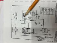
Next step is to take a look at the wiring diagram to determine if your furnace is "seeing" the voltage provided by your camper.

I have highlighted the two sources of 12V for the furnace on the wiring diagram. One is to the ckt board and the other is via the thermostat.
- Note, the requirement of the thermostat is 1AMP. If you have installed a new thermostat and that is not capable of 1AMP that could be an issue. (You can just connect the two wires on the back of the thermostat if you think that is a problem and see if the furnace works).
"On/Off Switch breaker" - You'll see on the wiring diagram on the left side the On/Off Switch breaker.
If is marked with"off" and "reset". The operating position is "reset." This switch/breaker "trips" if there is a short and to reset it you can cycle it to "off" and back to "reset." Note, your furnace may appear to operate with this switch is in the "off" position since there is another source of 12V being provided via the thermostat. In my opinion, the manual doesn’t explain that this switch should be normally set to “reset.” This could be a source of some folks issue that assume otherwise.
Trouble shooting power:
- Turn the main ckt breaker for the FWC back on or replace the blade.
- Cycle the furnace switch to "off" then back to "reset"
- Turn the thermostat on (switch to heat, auto and set temp above ambient)
- Measure voltage at two locations (red wire on the ckt board and both sides of the limit switch). Place the red multimeter wire on the location and black on metal frame of the furnace. The voltage should be the same as your battery or close.

Note: Test both sides of the limit switch. If one side has no volts then the limit switch may be faulty. (I'll go into detail on the next post). For the red wire, you may have to slip to multimeter probe into the plastic.
- Limit SWITCH voltage: If the voltage is zero or significantly less than your battery voltage then you may have a thermostat problem. Once again, you can remove your thermostat and connect the two wires to test.
- Power to the CKT Board (red wire): Should read same as battery voltage. If not, then On/Off breaker may not be in the correct position or the camper blade breaker has tripped.
I have read some of you have experienced the the furnace going through a normal sequence and then turning and then have the flame immediately go out. Based on the wiring diagram this could be caused by the switch/reset breaker being in the off and the power being provided by the thermostat 12V. This is only a guess since I don't have details on how the ckt board is wired. Make sure your switch is in the "reset" position.
Next post to follow will go into detail on diagnosing electrical safety features of the sail switch, limit switch and diagnostic led indications.
This is a follow - up on my original post regarding diagnosing an ATWOOD heater before replacing parts. This is my assessment and based on the installation/operation manual and troubleshooting my own furnace. Note, there are warnings in the manuals not to do your own troubleshooting and repairs. You could damage your furnace by conducting your own repairs. (I sound like a lawyer!) I am not an expert on ATWOOD furnaces other than I have electrical engineer degree, was in the Navy for 25 years and I'm an opinionated old man!
It appears that newer versions of the ATWOOD heater use the same logic and electric system....however I cannot confirm. I'm happy to get feedback or be told I'm incorrect with anything in this and follow-on posts
So let's get started.
I will divide this into three posts:
> ATWOOD FURNANCE and POWER
> Safety CKT (Limit Switch and Sail Switch)
> Propane and ignition
The sequence of the ATWOOD furnace to provide heat is:
- Power - (11-13.5 volts)
- Not too hot? = limit switch
- Air Flow ok? = sail switch
- Turn on propane
- Start igniter
I'll discuss power diagnosis and requirements first.
ATWOOD FURANCE and POWER:
To troubleshoot the furnace you will need three items. Multi-meter that can read direct 12Volts and continuity (Is the ckt on or off?), the tech manual (specifically the Wiring and Ladder diagram) and a 1/4 socket wrench. I suggest turning off 12Volts to the furnace via the main CKT breaker for the camper or pulling the blade fuse associated with the furnace.
Safety - 12Volts won't shock you....however the ignition to the electrode that creates a spark likely will. Don't touch the round black device on the ckt board with a red wire on top that connects to the electrode!
To open the furnace you can turn the grommet on the bottom of the furnace face 1/4 either way and pull out from the bottom.
Once open, the circuit board for the furnace is on the bottom right and has the sticker "ATWOOD MOBILE PRODUCTs". To access the board remove the 1/4 inch screw on the top and tilt the board outwards.
The manual states that the ATWOOD heater will operate with a voltage between 11V to 13.5V. To assess your current voltage available either measure the battery voltage using the multi-meter or via the display panel for your FWC.
Next step is to take a look at the wiring diagram to determine if your furnace is "seeing" the voltage provided by your camper.
I have highlighted the two sources of 12V for the furnace on the wiring diagram. One is to the ckt board and the other is via the thermostat.
- Note, the requirement of the thermostat is 1AMP. If you have installed a new thermostat and that is not capable of 1AMP that could be an issue. (You can just connect the two wires on the back of the thermostat if you think that is a problem and see if the furnace works).
"On/Off Switch breaker" - You'll see on the wiring diagram on the left side the On/Off Switch breaker.
If is marked with"off" and "reset". The operating position is "reset." This switch/breaker "trips" if there is a short and to reset it you can cycle it to "off" and back to "reset." Note, your furnace may appear to operate with this switch is in the "off" position since there is another source of 12V being provided via the thermostat. In my opinion, the manual doesn’t explain that this switch should be normally set to “reset.” This could be a source of some folks issue that assume otherwise.
Trouble shooting power:
- Turn the main ckt breaker for the FWC back on or replace the blade.
- Cycle the furnace switch to "off" then back to "reset"
- Turn the thermostat on (switch to heat, auto and set temp above ambient)
- Measure voltage at two locations (red wire on the ckt board and both sides of the limit switch). Place the red multimeter wire on the location and black on metal frame of the furnace. The voltage should be the same as your battery or close.
Note: Test both sides of the limit switch. If one side has no volts then the limit switch may be faulty. (I'll go into detail on the next post). For the red wire, you may have to slip to multimeter probe into the plastic.
- Limit SWITCH voltage: If the voltage is zero or significantly less than your battery voltage then you may have a thermostat problem. Once again, you can remove your thermostat and connect the two wires to test.
- Power to the CKT Board (red wire): Should read same as battery voltage. If not, then On/Off breaker may not be in the correct position or the camper blade breaker has tripped.
I have read some of you have experienced the the furnace going through a normal sequence and then turning and then have the flame immediately go out. Based on the wiring diagram this could be caused by the switch/reset breaker being in the off and the power being provided by the thermostat 12V. This is only a guess since I don't have details on how the ckt board is wired. Make sure your switch is in the "reset" position.
Next post to follow will go into detail on diagnosing electrical safety features of the sail switch, limit switch and diagnostic led indications.
Edited by Sledawg, 19 March 2024 - 09:38 PM.
2021 Off Road TACOMA 2013 FWC Fleet
Going Insane Diego!
Going Insane Diego!
#58
Sledawg
-
- Members
- 126 posts
Senior Member
Posted 19 March 2024 - 06:57 PM
LIMIT SWITCH - SAIL SWITCH - FAULT LIGHTS - FAN POWER
The next step in electrical diagnosis are the fan, limit and sail switch. 12V+ = Happy. 11V or less = Unhappy
FAN: The fan should start as soon as the thermostat is turned on and set.
If the fan is not working measure the voltage on the right side of the board for the "RED-ROUGE - the one that looks ORANGE" wire.
It should read the same or near to the camper battery voltage. If is 12V+ then the fan is bad or wiring to the fan is disconnected. If it is zero then the ckt board is faulty and there should be a fault light. Discussed later.
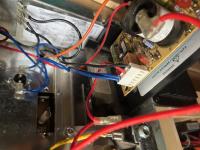
LIMIT SWITCH: The purpose of the limit switch is to measure if the furnace is too hot. If it is cool enough to start then the limit switch is closed. To determine if the limit switch is good, you can conduct a continuity check using the multi-meter. The setting is the one where if you put the two probes together the meter beeps and reads "1". This means it is a closed circuit. If the check reads zero or no "beep" the limit switch is bad. Another method is to measure the voltage on each side on the limit switch once the thermostat is on and it should read the same....12V+ or the same or near your camper battery. The limit switch is located at the top arrow on the picture below.
SAIL SWITCH: The purpose of the sail switch is all about "flow". Air flow to be exact. For you old men it is all about cash flow and another flow....but I digress.
Once the fan starts, the safety logic is "cool enuf = limit switch plus is there air flow? SAIL SWITCH. If there is sufficient air flow the sail switch closes the 12V ckt. To test you can measure the voltage at on the CKT board where the two blue wires attach. Measure the voltage at the first one, You can place the multimeter probe at the bottom the white connection below the wire.
12V = limit switch is doing its job providing the fan is on. Less than 10V = the limit switch is not measuring the air flow correctly or it is broken. Access to the sail switch requires removal of the entire furnace…not something I want to do.

FAULT LIGHTS: The CKT board has an LED that indicates faults. Similar to an "idiot light" on a car in my youth, it tells you something is wrong but not what it is.
The details of the fault light can be found on the bottom of page 6 of the manual.
Summary:
1 Flash - FLOW problems. Either limit switch or sail switch. Note, if the on/reset switch is in the wrong position you will see one flash.
2 Flashes - Flame sense fault
3 Flashes - Ignition fault
The manual doesn't explain what the flame sense or ignition faults mean or the resolution. My assumption is flame sense is it didn't light (no voltage to the propane valve) and ignition via the electrode failed (the round black item on the board didn't provide sufficient voltage or failed). Note on the CKT diagram there is no sensor or feedback associated with determining if there is a flame....that I can figure out.
My browsing of the internet indicated the most common failures for this furnace are the limit and sail switch. Hope this helps.
Next post - propane valve and ignition voltage....
The next step in electrical diagnosis are the fan, limit and sail switch. 12V+ = Happy. 11V or less = Unhappy
FAN: The fan should start as soon as the thermostat is turned on and set.
If the fan is not working measure the voltage on the right side of the board for the "RED-ROUGE - the one that looks ORANGE" wire.
It should read the same or near to the camper battery voltage. If is 12V+ then the fan is bad or wiring to the fan is disconnected. If it is zero then the ckt board is faulty and there should be a fault light. Discussed later.
LIMIT SWITCH: The purpose of the limit switch is to measure if the furnace is too hot. If it is cool enough to start then the limit switch is closed. To determine if the limit switch is good, you can conduct a continuity check using the multi-meter. The setting is the one where if you put the two probes together the meter beeps and reads "1". This means it is a closed circuit. If the check reads zero or no "beep" the limit switch is bad. Another method is to measure the voltage on each side on the limit switch once the thermostat is on and it should read the same....12V+ or the same or near your camper battery. The limit switch is located at the top arrow on the picture below.
SAIL SWITCH: The purpose of the sail switch is all about "flow". Air flow to be exact. For you old men it is all about cash flow and another flow....but I digress.
Once the fan starts, the safety logic is "cool enuf = limit switch plus is there air flow? SAIL SWITCH. If there is sufficient air flow the sail switch closes the 12V ckt. To test you can measure the voltage at on the CKT board where the two blue wires attach. Measure the voltage at the first one, You can place the multimeter probe at the bottom the white connection below the wire.
12V = limit switch is doing its job providing the fan is on. Less than 10V = the limit switch is not measuring the air flow correctly or it is broken. Access to the sail switch requires removal of the entire furnace…not something I want to do.
FAULT LIGHTS: The CKT board has an LED that indicates faults. Similar to an "idiot light" on a car in my youth, it tells you something is wrong but not what it is.
The details of the fault light can be found on the bottom of page 6 of the manual.
Summary:
1 Flash - FLOW problems. Either limit switch or sail switch. Note, if the on/reset switch is in the wrong position you will see one flash.
2 Flashes - Flame sense fault
3 Flashes - Ignition fault
The manual doesn't explain what the flame sense or ignition faults mean or the resolution. My assumption is flame sense is it didn't light (no voltage to the propane valve) and ignition via the electrode failed (the round black item on the board didn't provide sufficient voltage or failed). Note on the CKT diagram there is no sensor or feedback associated with determining if there is a flame....that I can figure out.
My browsing of the internet indicated the most common failures for this furnace are the limit and sail switch. Hope this helps.
Next post - propane valve and ignition voltage....
Edited by Sledawg, 19 March 2024 - 09:32 PM.
2021 Off Road TACOMA 2013 FWC Fleet
Going Insane Diego!
Going Insane Diego!
#59
craig333
-

- Members
- 8,022 posts
Riley's Human
- LocationSacramento
Posted 19 March 2024 - 08:20 PM
Nice work!
Craig K6JGV_________________________ 2004 2500 CTD 4X4 FWC HAWK 1960 CJ5
#60
Sledawg
-
- Members
- 126 posts
Senior Member
Posted 21 March 2024 - 09:10 PM
PROPANE AND IGNITION
The last step for the furnace to light off is the opening of the propane valve and providing a voltage to the electrode which creates a spark. It appears that this occurs simultaneously. The challenge is to figure out if the actual propane valve or electrode are not working if the electrical diagnosis is ok.
Propane Valve: To determine if the valve is getting at 12V signal measure the red wire connected to the propane valve. Either red wire connection can be measured on the valve. 12V indicates is the correct voltage and remains on until the temperature is reached. No or less than 10V indicates the CKT board may be bad. You can feel the valve open and if the furnace doesn't light, smell the propane at the exterior exhaust port. In that case the problem may be the electrode.

Electrode: The red wire on top of the round black object is the source of the spark for the electrode which creates the spark. You can measure the voltage provided to the electrode by setting the multi-meter to 200V. The voltage is not steady and will jump, You can usually hear the spark provided by the electrode. Note, to test the ignition you have to have the thermostat off and then on to commence the ignition sequence. I read on line some have removed the electrode and commenced the ignition sequence to see if there is a spark. That could risk having the propane light off in your face....not recommended.

So, if I have a problem again with my furnace, I'll start with the voltage checks for the limit switch and sail switch which are the most common issues. I can usually hear if the propane valve and electrode are working. Voltage checks are a good idea. Don't forget to ensure the reset switch is set to "reset." After that I would give the entire furnace a low pressure air cleaning.
I have gotten good "gouge" from the WTW website since I purchased my FWC in 2013 and I hope this helps someone in return. Do some diagnostics before just replacing parts. Good luck and I hope to see you on the backroads!

Edited by Sledawg, 21 March 2024 - 09:21 PM.
2021 Off Road TACOMA 2013 FWC Fleet
Going Insane Diego!
Going Insane Diego!


0 user(s) are reading this topic
0 members, 0 guests, 0 anonymous users

