Jump to content


Photo

Solar and AC Charging - Switch Needed?


  • Please log in to reply
8 replies to this topic

#1 Fishyhead

Fishyhead

    Advanced Member

  • Members
  • PipPipPip
  • 68 posts
  • LocationAnaheim, CA

Posted 05 May 2020 - 10:24 PM

I'm upgrading the solar panels, controller, and battery on my 1993 FWC Ranger and adding a converter to charge the battery while hooked up to shore power.


Question:

Should I install a switch between the battery, the solar controller, and converter to manually select which source I'm charging the battery with?


  • 0

1997 Toyota T100 4x4 manual - 1993 FWC Ranger 8'


#2 ckent323

ckent323

    Senior Member

  • Members
  • 1,227 posts
  • LocationSolvang, CA

Posted 06 May 2020 - 02:34 AM

The battery does not care where it gets recharge power from.  The battery does care that it gets charged according to the manufacturers specs.

If a lead acid battery that means fully recharging after discharging, before discharging again, as well as going through the appropriate charging stages (bulk, absorption, float).  LiFePO4 has it own specific needs.

It may make sense to put in a switch between the panels and the controller if you want to be able to isolate a part of the charge system for servicing, expansion or something.  

Victron and Pacific Yacht Systems have a number of generalized schematics available that show various configurations that you can borrow from.  They also have technical information that might be helpful.


Be sure to read the instructions for whatever solar controller and charger you use.  Some can be damaged if you switch the circuit when it is under load or power.


Edited by ckent323, 06 May 2020 - 05:29 AM.

  • 0

1993 Dodge Cummins W-250 Club Cab long bed, 2007 FWC Keystone


#3 PaulT

PaulT

    Need gumbo

  • Members
  • 2,611 posts
  • LocationHillsboro, Oregon

Posted 06 May 2020 - 02:48 AM


Be sure to read the instructions for whatever solar controller and charger you use.  Some can be damaged if you switch the circuit when it is under load or power.

+1 here. For example, some solar charge controllers state that they can be damaged if you have solar panels hooked up but not the battery.  In that case, you would put the switch between the solar panel and the controller rather than between the controller and the battery.


Paul


  • 0
I thought getting old would take longer.

#4 Fishyhead

Fishyhead

    Advanced Member

  • Members
  • PipPipPip
  • 68 posts
  • LocationAnaheim, CA

Posted 06 May 2020 - 03:36 AM

I picked up a Victron MPPT 100/30 controller, a Progressive Dynamics charger, and a Battle Born LiFePO4 battery to replace a Renogy PWM controller and FLA battery.


The two schematics I was looking at:

https://www.victrone...et-and-MPPT.pdf

https://www.exploris...agrams-archive/


treat the solar controller differently - Victron has it bypassing the switches to connect to the battery.  The explorist.life schematic places a switch between the controller and battery.  Both place a switch between the charger and battery.


It makes sense to place a switch between the battery and everything else so why does Victron bypass it?


  • 0

1997 Toyota T100 4x4 manual - 1993 FWC Ranger 8'


#5 Vic Harder

Vic Harder

    Doctor Electric

  • Site Team
  • 4,950 posts
  • LocationCalgary, Alberta

Posted 06 May 2020 - 03:57 AM

Both of those systems are way more complicated than what most will have in their rigs.  That said, you need to look at the function of the "switch".  Is it to isolate the PV panels, the controller?  The various charging source from the batteries?


Note that the Victron diagram has an "isolator" between the PV array and the controller.


I have not used switches or isolators between my PV array and my Victron 100/30 and dual BBorn batteries.


  • 0

#6 pvstoy

pvstoy

    Senior Member

  • Members
  • 2,768 posts
  • LocationCarson City, NV

Posted 06 May 2020 - 04:02 AM

You could not have found two of the most confusing and too complicated wiring diagrams as examples.  Somebody here will show a much simpler way shortly I'm sure.


  • 0

Patrick

2015 FWC Hawk Flatbed


#7 pvstoy

pvstoy

    Senior Member

  • Members
  • 2,768 posts
  • LocationCarson City, NV

Posted 06 May 2020 - 04:11 AM

Battery's don't care where they get their charge from as long as it is the proper one.  You do not really need a switch as first one with the most voltage/amps win and the other if it is a smart charger will back off and trickle into the battery thinking great I did my job.


By having a switch in the system as said above is for you to turn things on and off and for your convince and/or maintenance.  If you make it that you have to always turn things on and off, well, that is going to be old after a while and you cannot be more efficient then the smart system you can install.


  • 0

Patrick

2015 FWC Hawk Flatbed


#8 ckent323

ckent323

    Senior Member

  • Members
  • 1,227 posts
  • LocationSolvang, CA

Posted 06 May 2020 - 05:22 AM

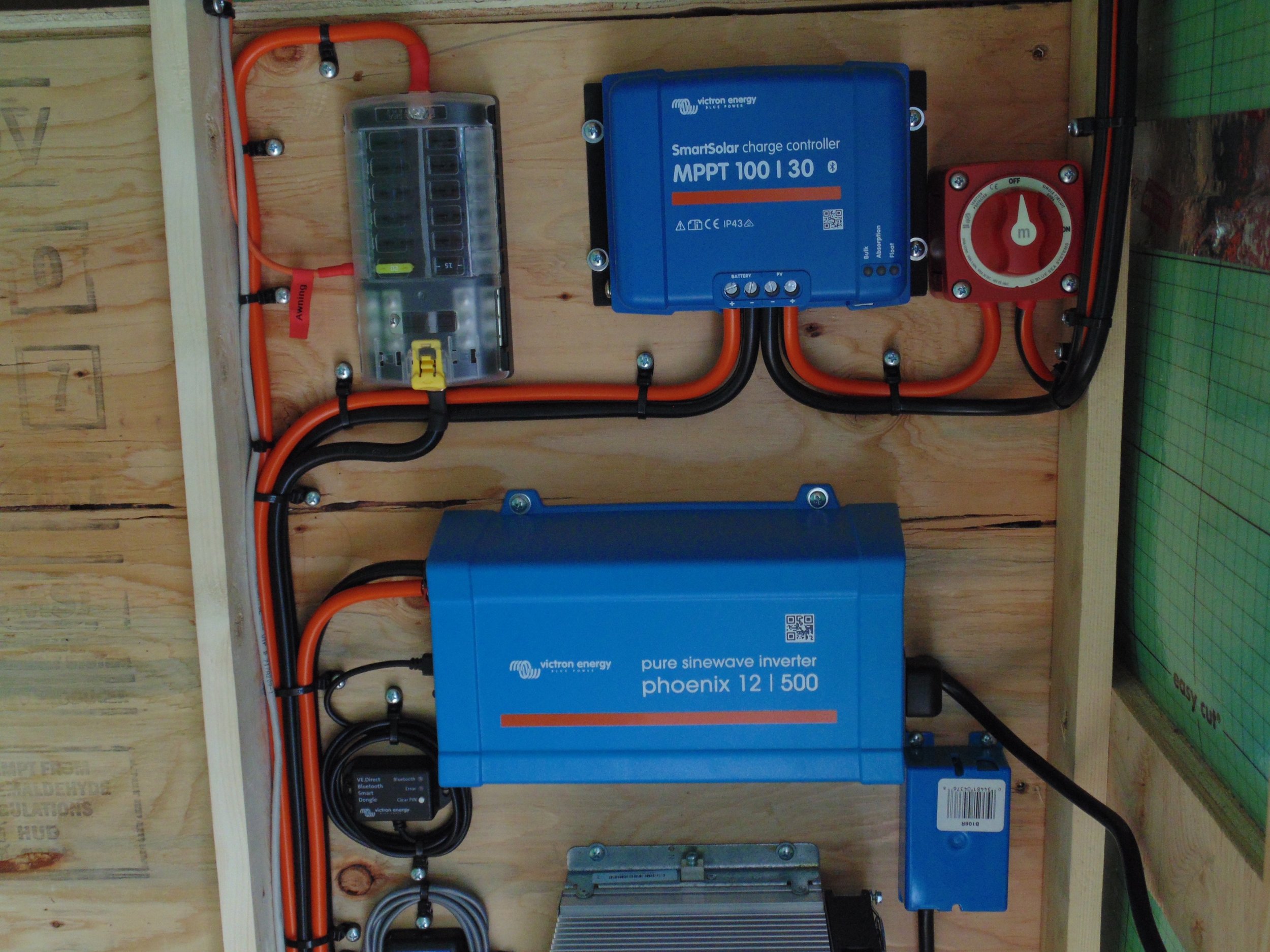
I have not seen switches used in any Victron example between the controller and the battery.  I have seen a PV isolator used between the panels and the Victron controller in the Victron examples but not a switch, although I see no reason one cannot be put there instead of an isolator.
 

Note: the Victron schematic diagram link above is for a large boat installation (BTW: I don't understand the need for the 40 A resettable breaker between the MPPT solar controller and the battery bank.  The bank is fused for protection as is the controller itself).

BTW:  In your 12v (or 24 V) system be sure to use DC rated fuses not AC fuses.  For example, your battery should be fused at or near the positive battery terminal


Below is a link to a system using Victron components that employs a switch between the panels and the MPPT controller.  This is not necessary but may be useful as an always on switch unless you need switch it off to add or trouble shoot the panels or the battery bank, as has been discussed above.


If you decide to add a switch read this (it seems a switch between the battery and the controller may not damage the controller - but you decide after reading):

https://community.vi...n-port-b-1.html


https://amsolar.com/...ategory/Trailer


Horse-Trailer-Solar-Victron.jpg


Edited by ckent323, 06 May 2020 - 05:57 PM.

  • 0

1993 Dodge Cummins W-250 Club Cab long bed, 2007 FWC Keystone


#9 Fishyhead

Fishyhead

    Advanced Member

  • Members
  • PipPipPip
  • 68 posts
  • LocationAnaheim, CA

Posted 06 May 2020 - 07:45 PM

Thanks for the replies and links. I've got a much better understanding of how I'll want to wire this up. I will end up putting a switch and fuse between the PV panels and the controller and wire the controller's output though a fuse to main positive bus where the charger will be connected to as well though its own fused wire. I'll install a switch and fuse between the battery and main bus. An additional switch between the charger and positive bus seems unnecessary since I can turn the charger on/off at the AC breaker box.

Edited by Fishyhead, 06 May 2020 - 07:48 PM.

  • 0

1997 Toyota T100 4x4 manual - 1993 FWC Ranger 8'


0 user(s) are reading this topic

0 members, 0 guests, 0 anonymous users